Also for all this work you HAVE to have an upright column driller, or it will be impossible to make a good work.


After this it was OK.
But as the screws used are supposed to fit IN the face, I decided to enlarge the first half of the hole with a larger bit and then use the dremel for finish :

Aaaaaaand much better :

That's when I've seen this (but it was advertised in Ruckus documentation anyway) :

The front lips of the enclosure are too high for the VU-meter place. So, Dremel in saw mode again.

- I was now able to put the front panel board together
As I have ordered the same pots than Rucks, I used the adapter boards. Soldered three leads on them :

Assembling the led bargraph on its sockets

First assembly without soldering

Making that fit in the face, putting the mounting screws on pot to hold them tight. I verified the position of the switches did fit the front face marking by putting knobs on them and trying the positions.
And then soldering :


In my case the led bargraph sockets barely touched the IC board. I was able to solder it anyway :

But then for the next step of soldering the controller socket, I had a really hard time, as on the opposite side the sockets did go very high from the board, as my Iron almost didn't fit between the two sockets. Anyway, I managed to do it without damaging the sockets that much.
I assembled all of the front face items then.
I noticed the Lorlin switches were a bit too long for my knobs, so I trimmed them to the same length as the honeywell with my wire cutters

- On the next part is where I really screwed up on this build.
I determined the position of back face elements roughly. My IEC socket hole was too little for the BOM IEC I ordered (with fuse apparent) so I had to enlarge it, and also to enlarge the screw holes a little to make them tighter to the IEC hole, as the existing holes were too far from each other to fit my socket.

And after a lot of drilling (many little drillings around the socket positions, increasing size of bits) and a lot of bad dremel job (was my first real dremel job and I ripped off A LOT) here you go :

Actually this side was supposed to be the inner side (not visible), but I screwed up the other side so much (you won't see it :D except if you look a little bit after) I decided to switch, even if the progressive holes for mouting will be not usable (I will use standard screws instead, not really a problem).
This part was for me the most exhausting and frustrating, and it took me a while (something like 4-5 hours just for doing the back face). I think my neighbours hate me (I live in a flat).
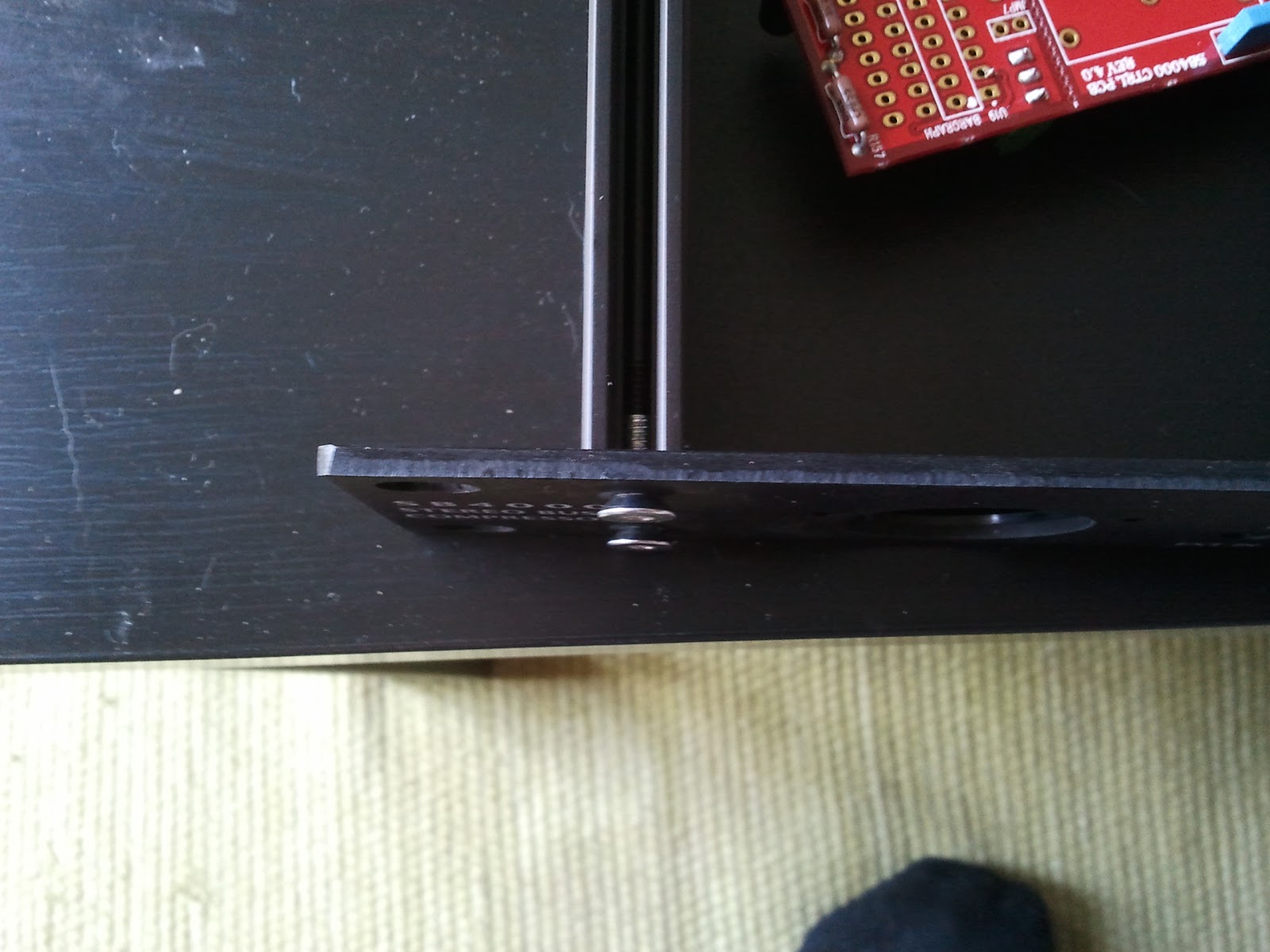
I verified the hole I made for the ground was having good contact between the inside of the face (without alodine) and the screw I'll fit in (I enlarged it a little with a file to insure good contact). For this I used my multimeter on continuity mode again.

As you can see I used TS jack for Send/Return. The rackmount neutrik TS jack females I got were not fitting nicely, the back face of the rack being too deep. The two parts of the jack sockets were unable to lock together. So using cutters I trimmed a part of them :

On one of them I trimmed too much so it was not locking enough anymore and the parts were loose (manipulating the jack a lot would have permitted to break the inner soldering). So I used small parts of gaffer on the inner face ("If gaffer can't fix it, nothing can"©) to add some distance between the two parts and after that they did lock nicely.
- Finished the drilling


Verifying the mounting board adjustment :


Insuring a good ground connection between all parts (validated with my multimeter in continuity mode)


That's when I noticed the PSU board biggest capacitors were quite touching the top part of the enclosure (the top part is quite bending).

I'll have to find a way to ensure they won't touch.
That's where I am right now !! Worked on this for 2 evenings and 2 complete days.
Aucun commentaire:
Enregistrer un commentaire