Hi all,
Due to some changes in my professional / personal life, I'm selling a big part of my hardware, including this SB4000 I've built. All informations concerning this item can be found here I think, so if you are interested let me know.
mardi 10 septembre 2013
mercredi 4 juillet 2012
SB4000 Quad VCA Recap Post
This is only a recap post.
The complete Quad VCA BOM (revised after the build for better accuracy) :
Quad VCA BOM
How it did go before the build (sourcing, pricing and stuff) :
The start
More Orders
Mouser taxes and final price
Ready to go
The build itself :
Part I
Part II
Part III
Part IV
Part V
The complete Quad VCA BOM (revised after the build for better accuracy) :
Quad VCA BOM
How it did go before the build (sourcing, pricing and stuff) :
The start
More Orders
Mouser taxes and final price
Ready to go
The build itself :
Part I
Part II
Part III
Part IV
Part V
SB4000 Quad VCA BOM
Here is a public Google Docs BOM with every single thing I used to make this build. It combines the official SB 4000 BOM, the official Quad VCA BOM changes, and some stuff wrong or forgotten on those BOMs (like pins / sockets for mounting quad boards etc...). I fixed it AFTER the build, so it can be really accurate.
There are most of the mouser / manufacturer references, except for some resistors / capacitors. I used quite different providers / values (some caps were upgraded to higher voltage, some not) for those which are empty, so I guess it's better if you take everything from the same provider, that's why I left them empty.
Note that quantities for the Quad VCA part are TOTAL (including the 2 boards, unlike the official Quad VCA BOM).
Also my version uses 2 Jack TS (unbalanced signal) for Send / Return, and I blended L & R on both so it's a Mono External Sidechain (which seems simpler to me than the XLR version everyone else made which must use and adapter to have all signals parted)
Here you go : SB4000 Quad VCA compiled BOM
USE IT AS A REFERENCE FOR YOUR BUILD, as many items values differ from the informations shown on the boards.
Feel free to let me know if you find anything wrong in there !
SB4000 Quad VCA Part V : Up and running
Hi again !
I found the issue, it was quite stupid : The ribbon cable was mounted backward. I mounted like I thought a ribbon cable should be mounted, without watching the pin 1 dots on the boards.
So I unmounted it and remounted it in the correct way :

After this the unit worked much better (controls were correct and I was able to pass calibration step 3). But I still had not response from the LED Bargraph.
I unmounted it and saw it was mounted backward too. In fact, when mounting it, I looked to see if I saw a Pin 1 dot on it and was unable to find it, so I assumed it was possible to mount it either way. But I must have been tired because there is a Pin 1 dot on it :)
While I got the control board unmounted I saw that JMP7 was empty and I remembered it must be jumped in order to have normal bargraph behaviour (not dot style) so I installed a 2 pin socket and a jumper (so I can test the other mode if I want).
This done, the unit was working perfectly, and I was able to do all calibration. I had a hard time to calibrate the bargraph because it was always to the max for the Input level but then I noticed I mounted Trim Pots in its section with "R In L In R Out L Out" on them. So I was able to adjust all that to have a correct behaviour on all Bargraph modes.
I played with it on a drum buss, man, this thing is awesome. I was able to have like 14 db of reduction without too much shitty artefacts in T2 mode. Won't work on a very speed metal drums, but on standard drum playing it seems incredible. Can't wait to use it in real recordings / mixes.
After this I cleaned and finished the unit (including shrinking tubes, I wanted to do that only after I'm sure all is wired correctly) :

And finished the mounting :

I feared the top plate would be close to touch the transformer screw but it's not the case, even when pushing it a little. I wanted to buy some L brackets to screw the back face to the top and bottom plates but I don't think I will do it as it would mean unmount all the XLRs and stuff to be able to drill new holes. I'll use it this way and see if it's reallly an issue.
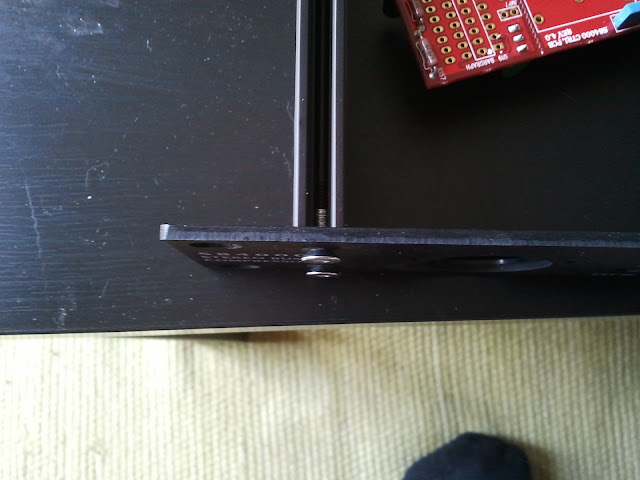
The Modushop case is the only thing I think I'm not fond of because of this missing solidarity between back face and top / bottom plates. The back face can be pretty loose in all directions : in front / back direction when pulling / pushing XLRs in/out and even in up / down direction as shown on this very ugly picture :

(Though for this one it's not that bad when top plate is mounted).
The only thing left is to buy 2 more pot nuts for the honeywell pots, as they don't come with any so they are quite loose. It's standard M10 * 0.75 nuts.
I'll post a recap soon with my own Quad VCA BOM with absolutely everything needed in it.

After this the unit worked much better (controls were correct and I was able to pass calibration step 3). But I still had not response from the LED Bargraph.
I unmounted it and saw it was mounted backward too. In fact, when mounting it, I looked to see if I saw a Pin 1 dot on it and was unable to find it, so I assumed it was possible to mount it either way. But I must have been tired because there is a Pin 1 dot on it :)
While I got the control board unmounted I saw that JMP7 was empty and I remembered it must be jumped in order to have normal bargraph behaviour (not dot style) so I installed a 2 pin socket and a jumper (so I can test the other mode if I want).
This done, the unit was working perfectly, and I was able to do all calibration. I had a hard time to calibrate the bargraph because it was always to the max for the Input level but then I noticed I mounted Trim Pots in its section with "R In L In R Out L Out" on them. So I was able to adjust all that to have a correct behaviour on all Bargraph modes.
I played with it on a drum buss, man, this thing is awesome. I was able to have like 14 db of reduction without too much shitty artefacts in T2 mode. Won't work on a very speed metal drums, but on standard drum playing it seems incredible. Can't wait to use it in real recordings / mixes.
After this I cleaned and finished the unit (including shrinking tubes, I wanted to do that only after I'm sure all is wired correctly) :

And finished the mounting :

I feared the top plate would be close to touch the transformer screw but it's not the case, even when pushing it a little. I wanted to buy some L brackets to screw the back face to the top and bottom plates but I don't think I will do it as it would mean unmount all the XLRs and stuff to be able to drill new holes. I'll use it this way and see if it's reallly an issue.
The Modushop case is the only thing I think I'm not fond of because of this missing solidarity between back face and top / bottom plates. The back face can be pretty loose in all directions : in front / back direction when pulling / pushing XLRs in/out and even in up / down direction as shown on this very ugly picture :

(Though for this one it's not that bad when top plate is mounted).
The only thing left is to buy 2 more pot nuts for the honeywell pots, as they don't come with any so they are quite loose. It's standard M10 * 0.75 nuts.
I'll post a recap soon with my own Quad VCA BOM with absolutely everything needed in it.
mardi 3 juillet 2012
SB4000 Quad VCA part IV : Wiring / Firing up / Troubleshooting
Hi again !
I managed to "finish" the build yesterday.
- I found a better screw for the transformer :

- I also replaced the standoffs by an assembly of nuts / washers to lower the level of the PSU board, as suggested by Wave on the groupDIY forum :

- I mounted the heatsinks

- Wiring XLR / Jacks

- Wiring the transformer
I used the BOM suggested transformer. Here are the infos :


So for 230V I had to tie Gray to Violet :

Then I heated the shrink-tube to cover the wires.
I found this schema on the forum which explain how transformer / fuse / IEC should be connected :
 Even the position on the switch is important. As it is, the live will only be present in the rack when the switch is engaged. If they were reversed, it would come to the switch in all cases.
In my case Live is Blue and Neutral is brown.
BEWARE : On following pictures I've just noticed that I DID exchange the position on the Power Switch, so please not it's correct.
- Some switches wiring (As explained later, the NKK switches seem to be correct, but not sure about the I/O L/R ones).

- Aaaaaaand everything wired (except PSU board to Main board and the chips that I added after checking PSU voltages). Please not the fact that I disconnect from the PSU side, not the other, in order to avoid having voltage through the disconnected wires.

- Don't forget to put the fuse or it won't work that great :) And DON'T FORGET TO PUT EVERY GROUND WIRES ON THE GROUND STAR BEFORE ADDING IEC Cord !!

- My voltages were ok for +-12, but I only got -12 and +12 values for +-15 points. So I adjusted with the trim pots (strange though I had so low voltages as I pre-trimmed them to 1K33 as advised) to obtain +-15.
I then connected PSU board to Main board (disconnected control board). Again, all voltages were correct and stable, and VUMeter did light up in blue. I added the control board, and again the voltages were correct.
My Push button for Stereo/Mono Sidechain was not working properly, but it was due to the fact I did not screw its wire in the connector properly.
Unit passed audio on both channel. I was able to take step 2 (Unity gain) of Calibration correctly (even when Compressor In I have some distortion). But I'm stuck at Step 3, as I can't adjust TP12 to read the same as TP10. With the pot fully trimmed, I still got lower value than TP10. I have to find out why it is so. Both channels don't react the same, so something must have gone wrong during component implant or soldering on one of the channels.
Also at this step I noticed I might have wired Ext In switch the wrong way (In seems to be on the down). Maybe all those 3 switches are wrong, I'll see when I'll be there.
I'll let you know when I'll go further !!
I managed to "finish" the build yesterday.
- I found a better screw for the transformer :

- I also replaced the standoffs by an assembly of nuts / washers to lower the level of the PSU board, as suggested by Wave on the groupDIY forum :

- I mounted the heatsinks

- Wiring XLR / Jacks

- Wiring the transformer
I used the BOM suggested transformer. Here are the infos :

So for 230V I had to tie Gray to Violet :

Then I heated the shrink-tube to cover the wires.
I found this schema on the forum which explain how transformer / fuse / IEC should be connected :
In my case Live is Blue and Neutral is brown.
BEWARE : On following pictures I've just noticed that I DID exchange the position on the Power Switch, so please not it's correct.
- Some switches wiring (As explained later, the NKK switches seem to be correct, but not sure about the I/O L/R ones).

- Aaaaaaand everything wired (except PSU board to Main board and the chips that I added after checking PSU voltages). Please not the fact that I disconnect from the PSU side, not the other, in order to avoid having voltage through the disconnected wires.

- Don't forget to put the fuse or it won't work that great :) And DON'T FORGET TO PUT EVERY GROUND WIRES ON THE GROUND STAR BEFORE ADDING IEC Cord !!

- My voltages were ok for +-12, but I only got -12 and +12 values for +-15 points. So I adjusted with the trim pots (strange though I had so low voltages as I pre-trimmed them to 1K33 as advised) to obtain +-15.
I then connected PSU board to Main board (disconnected control board). Again, all voltages were correct and stable, and VUMeter did light up in blue. I added the control board, and again the voltages were correct.
My Push button for Stereo/Mono Sidechain was not working properly, but it was due to the fact I did not screw its wire in the connector properly.
Unit passed audio on both channel. I was able to take step 2 (Unity gain) of Calibration correctly (even when Compressor In I have some distortion). But I'm stuck at Step 3, as I can't adjust TP12 to read the same as TP10. With the pot fully trimmed, I still got lower value than TP10. I have to find out why it is so. Both channels don't react the same, so something must have gone wrong during component implant or soldering on one of the channels.
Also at this step I noticed I might have wired Ext In switch the wrong way (In seems to be on the down). Maybe all those 3 switches are wrong, I'll see when I'll be there.
I'll let you know when I'll go further !!
lundi 2 juillet 2012
SB4000 Quad VCA part III : Preparing the enclosure and assembling front panel
- My enclosure was a Modushop one. I had to drill the exterior pilot holes on the front face to make it fit. For every holes in metal, you have to increase size of holes step by step to have the hole precisely where you need it. You also have to punch the position of the hole before (for this one it was pre-drilled but for all the back face and the rest of the enclosure it was important). The most important drilling is the first one. You have to use a bit as little as possible. During my drilling I broke the most little bit, I had to use one just a little larger, and it was a pain in the ass to not have the driller move.
Also for all this work you HAVE to have an upright column driller, or it will be impossible to make a good work.


After this it was OK.
But as the screws used are supposed to fit IN the face, I decided to enlarge the first half of the hole with a larger bit and then use the dremel for finish :

Aaaaaaand much better :

That's when I've seen this (but it was advertised in Ruckus documentation anyway) :

The front lips of the enclosure are too high for the VU-meter place. So, Dremel in saw mode again.

- I was now able to put the front panel board together
As I have ordered the same pots than Rucks, I used the adapter boards. Soldered three leads on them :

Assembling the led bargraph on its sockets

First assembly without soldering

Making that fit in the face, putting the mounting screws on pot to hold them tight. I verified the position of the switches did fit the front face marking by putting knobs on them and trying the positions.
And then soldering :


In my case the led bargraph sockets barely touched the IC board. I was able to solder it anyway :

But then for the next step of soldering the controller socket, I had a really hard time, as on the opposite side the sockets did go very high from the board, as my Iron almost didn't fit between the two sockets. Anyway, I managed to do it without damaging the sockets that much.
I assembled all of the front face items then.
I noticed the Lorlin switches were a bit too long for my knobs, so I trimmed them to the same length as the honeywell with my wire cutters

- On the next part is where I really screwed up on this build.
I determined the position of back face elements roughly. My IEC socket hole was too little for the BOM IEC I ordered (with fuse apparent) so I had to enlarge it, and also to enlarge the screw holes a little to make them tighter to the IEC hole, as the existing holes were too far from each other to fit my socket.

And after a lot of drilling (many little drillings around the socket positions, increasing size of bits) and a lot of bad dremel job (was my first real dremel job and I ripped off A LOT) here you go :

Actually this side was supposed to be the inner side (not visible), but I screwed up the other side so much (you won't see it :D except if you look a little bit after) I decided to switch, even if the progressive holes for mouting will be not usable (I will use standard screws instead, not really a problem).
This part was for me the most exhausting and frustrating, and it took me a while (something like 4-5 hours just for doing the back face). I think my neighbours hate me (I live in a flat).
I verified the hole I made for the ground was having good contact between the inside of the face (without alodine) and the screw I'll fit in (I enlarged it a little with a file to insure good contact). For this I used my multimeter on continuity mode again.

As you can see I used TS jack for Send/Return. The rackmount neutrik TS jack females I got were not fitting nicely, the back face of the rack being too deep. The two parts of the jack sockets were unable to lock together. So using cutters I trimmed a part of them :

On one of them I trimmed too much so it was not locking enough anymore and the parts were loose (manipulating the jack a lot would have permitted to break the inner soldering). So I used small parts of gaffer on the inner face ("If gaffer can't fix it, nothing can"©) to add some distance between the two parts and after that they did lock nicely.
- Finished the drilling


Verifying the mounting board adjustment :

I noticed the transformer screw had a too thick head, will find a replacement :

Insuring a good ground connection between all parts (validated with my multimeter in continuity mode)


That's when I noticed the PSU board biggest capacitors were quite touching the top part of the enclosure (the top part is quite bending).

I'll have to find a way to ensure they won't touch.
That's where I am right now !! Worked on this for 2 evenings and 2 complete days.
Also for all this work you HAVE to have an upright column driller, or it will be impossible to make a good work.


After this it was OK.

But as the screws used are supposed to fit IN the face, I decided to enlarge the first half of the hole with a larger bit and then use the dremel for finish :

Aaaaaaand much better :

That's when I've seen this (but it was advertised in Ruckus documentation anyway) :

The front lips of the enclosure are too high for the VU-meter place. So, Dremel in saw mode again.

- I was now able to put the front panel board together
As I have ordered the same pots than Rucks, I used the adapter boards. Soldered three leads on them :

Assembling the led bargraph on its sockets

First assembly without soldering

Making that fit in the face, putting the mounting screws on pot to hold them tight. I verified the position of the switches did fit the front face marking by putting knobs on them and trying the positions.
And then soldering :


In my case the led bargraph sockets barely touched the IC board. I was able to solder it anyway :

But then for the next step of soldering the controller socket, I had a really hard time, as on the opposite side the sockets did go very high from the board, as my Iron almost didn't fit between the two sockets. Anyway, I managed to do it without damaging the sockets that much.
I assembled all of the front face items then.
I noticed the Lorlin switches were a bit too long for my knobs, so I trimmed them to the same length as the honeywell with my wire cutters

- On the next part is where I really screwed up on this build.
I determined the position of back face elements roughly. My IEC socket hole was too little for the BOM IEC I ordered (with fuse apparent) so I had to enlarge it, and also to enlarge the screw holes a little to make them tighter to the IEC hole, as the existing holes were too far from each other to fit my socket.

And after a lot of drilling (many little drillings around the socket positions, increasing size of bits) and a lot of bad dremel job (was my first real dremel job and I ripped off A LOT) here you go :

Actually this side was supposed to be the inner side (not visible), but I screwed up the other side so much (you won't see it :D except if you look a little bit after) I decided to switch, even if the progressive holes for mouting will be not usable (I will use standard screws instead, not really a problem).
This part was for me the most exhausting and frustrating, and it took me a while (something like 4-5 hours just for doing the back face). I think my neighbours hate me (I live in a flat).
I verified the hole I made for the ground was having good contact between the inside of the face (without alodine) and the screw I'll fit in (I enlarged it a little with a file to insure good contact). For this I used my multimeter on continuity mode again.

As you can see I used TS jack for Send/Return. The rackmount neutrik TS jack females I got were not fitting nicely, the back face of the rack being too deep. The two parts of the jack sockets were unable to lock together. So using cutters I trimmed a part of them :

On one of them I trimmed too much so it was not locking enough anymore and the parts were loose (manipulating the jack a lot would have permitted to break the inner soldering). So I used small parts of gaffer on the inner face ("If gaffer can't fix it, nothing can"©) to add some distance between the two parts and after that they did lock nicely.
- Finished the drilling


Verifying the mounting board adjustment :


Insuring a good ground connection between all parts (validated with my multimeter in continuity mode)


That's when I noticed the PSU board biggest capacitors were quite touching the top part of the enclosure (the top part is quite bending).

I'll have to find a way to ensure they won't touch.
That's where I am right now !! Worked on this for 2 evenings and 2 complete days.
SB4000 Quad VCA Part II : Cleaning, trim pots and Ribbon Cable
- Cleaning time :

I used the toothbrush to clean most of the flux / solder left on the board. Also you have to know, I usually clean all the flux projects after each soldering, with my finger nails :D
After that, I used compresses with alcohol to clean most of the boards by pressing it gently against it. On the particularly dirty parts, I used coton stretches (beware not to put too many alcohol on them or they will fall apart on the board quickly). After this, another round of hard toothbrush, and I considered it done.
- I part the 2 boards (the third was part already by Ruckus prior to shipping). The DREMEL was a bit of an overkill but I wanted to test my new toy ^^

- I was now ready to put trim pots everywhere, after pre-trimming them (VR1/VR2 on quad board to 5k, VR18/VR19 to 1k33 and the other to their maximum resistor values).
To trim pots I watched a video on youtube explaining I had to put my red probe on lead 2, and my black probe on lead 3. Then I adjusted to the desired value
 All pots in :

- For the Ribbon Cable I referred to this PDF found on groupDIY forum (you must be logged in) : Here


I used what I got on hand to put pressure on it (be careful to be as upright as possible when you put higher pressure ). When it clicks, it's ready !!
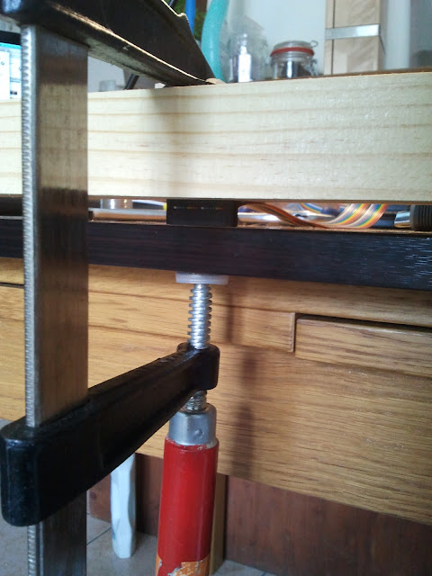
Be careful to have the 2 connectors watching in the same direction for this build (I did them opposed at first as it seemed natural to me, without watching pin 1 dots on sockets, and my unit was not working properly).
This is correct (and many other pictures are not, take care) :

I then tested with my multimeter in continuity mode (or you can use it in ohm meter and check you got near zero resistance) and 2 broken resistor leads (as my probes can't go in there) to ensure each pin was correctly connected to the opposite part :


Also I was quite surprised to see that the corresponding holes are not symetrically opposed, they're in the same spot on each part, I hope it's normal :)
To add the second part on top of it no need for tools, it's quite easy. Don't pull on the cable too much :


I used the toothbrush to clean most of the flux / solder left on the board. Also you have to know, I usually clean all the flux projects after each soldering, with my finger nails :D
After that, I used compresses with alcohol to clean most of the boards by pressing it gently against it. On the particularly dirty parts, I used coton stretches (beware not to put too many alcohol on them or they will fall apart on the board quickly). After this, another round of hard toothbrush, and I considered it done.
- I part the 2 boards (the third was part already by Ruckus prior to shipping). The DREMEL was a bit of an overkill but I wanted to test my new toy ^^

- I was now ready to put trim pots everywhere, after pre-trimming them (VR1/VR2 on quad board to 5k, VR18/VR19 to 1k33 and the other to their maximum resistor values).
To trim pots I watched a video on youtube explaining I had to put my red probe on lead 2, and my black probe on lead 3. Then I adjusted to the desired value


- For the Ribbon Cable I referred to this PDF found on groupDIY forum (you must be logged in) : Here


I used what I got on hand to put pressure on it (be careful to be as upright as possible when you put higher pressure ). When it clicks, it's ready !!

Be careful to have the 2 connectors watching in the same direction for this build (I did them opposed at first as it seemed natural to me, without watching pin 1 dots on sockets, and my unit was not working properly).
This is correct (and many other pictures are not, take care) :

I then tested with my multimeter in continuity mode (or you can use it in ohm meter and check you got near zero resistance) and 2 broken resistor leads (as my probes can't go in there) to ensure each pin was correctly connected to the opposite part :


Also I was quite surprised to see that the corresponding holes are not symetrically opposed, they're in the same spot on each part, I hope it's normal :)
To add the second part on top of it no need for tools, it's quite easy. Don't pull on the cable too much :

Inscription à :
Articles (Atom)